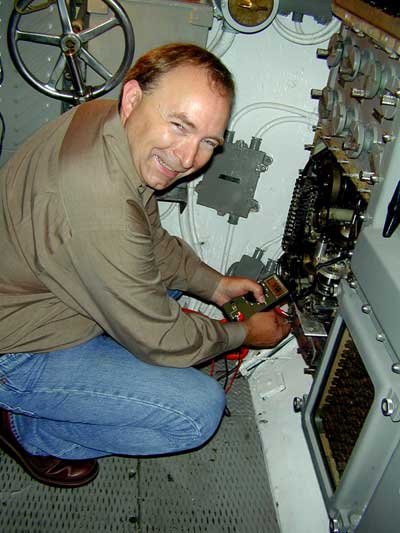
In late June (2003) Terry Lindell was finally able to come to Cleveland to inspect Cod's TDC in anticipation of restoring it and bringing it back on line. Because this device is designed and built with exceptionally close tolerances it is a delicate instrument and must be in perfect working order and properly maintained to provide the needed accuracy for aiming Cod's torpedoes. Thanks to Terry, Cod's Mark IV TDC is again fully operational!

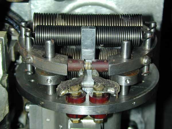
The second photo shows the upper section of the Position Keeper opened for inspection. This is the section that displays the computed relationships between Cod and a target ship. The dial in the middle of the top row shows the relative orientation of the target as determined by the TDC. Two small arrows indicate the angle at which torpedoes fired from either end of the submarine will hit the target. The letters "P" and "S" indicate the port and starboard sides of the target. The dial immediately below (in the second row) shows Cod's relative position. Again, there are two small arrows that show the course angle for the two torpedo tracks relative to Cod.
The dial in the upper left indicates the target ship's speed while the counter directly below that dial is the target's present range (distance from Cod). Other dials indicate other tactical data.

The photo above shows the lower section of the Position Keeper. Here you can see a few of the many gears and other mechanical components that do the calculating. At the very bottom and to the right of center is a thermostatically regulated electrical heater that maintains the temperature of this section so that mechanical clearances remain the same.
This is a close-up of the speed govenor mechanism (element 24 in the schematic below) for the TDC's time generating motor (element 23). The accuracy of the entire TDC depends on the accuracy of this regulator.
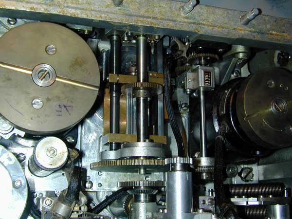
In the center of this photo is is a close-up of one of the mechanical integrators. This component actually performs mathematical integration -- a Calculus function! The Position Keeper uses eight of these components, (see elements 14, 15, 20, 25, 35, 36, 46 and 74 in the diagram below). .
This is a schematic diagram of Cod's Mark 4 TDC. Note that there are duplicate Gyro Angle Solver sections -- one for each of the torpedo tube nests at either end of the boat. These two sections are identical so are not repeated in the diagram.
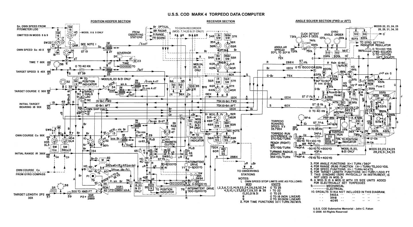
Principle Parameters: A - target angle; B - true target bearing; Br - relatve target bearing (periscope or TBT); C - target course; Co - own course; Fr - relative target bearing (sound/SONAR); G - gyro angle; H - target run; I - impact angle; J - torpedo advance; M - torpedo reach; R - range; S - target speed; So - own speed; T - time; U - torpedo run; Z - torpedo turning radius
Each of the solid black lines in the diagram is a shaft representing a mechanical value, usually indicated by the angle of rotation of the shaft. (Dashed lines represent electrical signals carried by wiring.) For example, in the upper left area of the diagram the shaft labeled So represents the present speed of the submarine. That value is being provided by a mechanical output from Cod's Pitometer Log, though it can also be manually set with a hand crank (element 21). As Cod's speed changes, the rotation angle of the So shaft changes accordingly. That shaft is an input to a mechanical integrator (element 20) and provides the variable of integration. The disk of the integrator is driven by the clock motor (element 23) and provides the time parameter (dT) for integration. The rotation of the output shaft is therefore proportional to the integral (summation) of the speed X time, or distance, that Cod has travelled since the clock was started.